Week 6: Embedded programming
The assignment:
1. Group assignemt: Browse through the data sheet for your microcontroller and compare the performance and development workflows for other architectures
2. Individual assignment: Write a program for a microcontroller development board that you made, to interacte and communicate
How I programmed my board to interact and communicate
The setup: First I connected the Seed to the PC (press and hold the Boot button) and made sure the "RPI-RP2" disk was shown on the PC. Now the hardware was connected. Then I added Seeed Studio XIAO RP2040 board to my Arduino IDE like this: (From the tutorial) Navigate to File > Preferences, and fill Additional Boards Manager URLs with the url below: https://github.com/earlephilhower/arduino-pico/releases/download/global/package_rp2040_index.json
Then I installed it from the Boards manager and selected the board and the port.
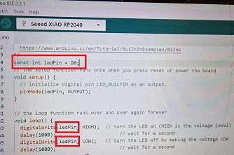
Doing the blink test:
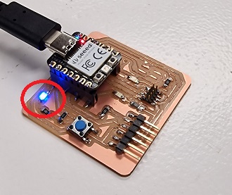
In order to connect my PC to my PCB I added the XIAO RP-2040 board to the list of boards in the Arduino software with the Board manager. Having done that I uploaded the Blink program to the board. Unfortunately is was the RP-2040 that blinked and not the LED on my board. Therefor I made som changes to the code. To get all this done I relied on the tutorial on Github and the help of my fellow students. And then it worked.
Click here to download the Source Code.
Controlling the LED with pushbotton
Next thing was to upload code to control the on/off of a LED using the pushbutton. First I defined the number of the pins for the LED and the Pushbotton by looking at the shematic overview from the Quentorres page.
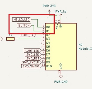
(Ledpin = D0, Buttonpin = D1). Then I set the LEDpin to an output and the Buttonpin as an input. DigitalRead is about reading whether the voltage on the pins is above or below a certain threshold. I set the button state to 0. BottonRead is about whether the botton is pressed or not. So if the bottonstate is HIGH (above 0 – not pressed) it turns off and if the botton is LOW (0 – pressed) it will turn on.
Click here to download the Source Code.
Here is the result:
Some of my struggles
My board is the Quentorres board with a Seeed RP2040 on it. I build it in week 4 when we did electronic production. I had some difficulties getting started and it seems that there was a number of things that made the setup difficult. During the process I found out - that cable I used had a loose connection - When I plugged in the RP2040 the ports disappeared - The Arduino IDE version 2.3.2 wouldn’t let me save the URL to an additional board. I tried to solve it by looking at the Seeed page: https://wiki.seeedstudio.com/XIAO-RP2040-with-Arduino/ and in the Arduino forum. And I made it work, but not by changing one particular thing, more like changing the cable, connecting, disconnecting, rebooting, etc. This left in a state where I didn’t know how I fixed it. Next day at the Lab, - the same issues, - sometimes it worked and sometimes it didn’t. I consulted my instructor and together we solved it by installing an earlier version of Arduino IDE - 1.8.19. Now the problem with the ports was gone. And everything seemed OK. But when I got home the Board wasn’t there as an option in Arduino anymore and I tried to install again. This time: Could not write preferences file: C:\Users\NISC\AppData\Local\Arduino15\preferences.txt (Access is denied). I went to the Arduino forum and here I could read that it could be a security thing and that I should try to add the item to exclusions –Here I found that “changing exclusions has been disabled by your administrator” (my PC is a work-PC). – Just to see, I opened the 2.3.2 version and now it found the board and a port. I haven’t found out why there is so much “sometimes it works and sometime it doesn’t”. But I could programme the board for now.
Using a Arduino board
I had no problems using a Arduino board
Inspired by the Arduino projects book I used an Arduino Uno to make a motor spin by pressing a button. I used these components:
I used this shematics to connect:
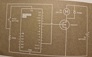
This is how it worked
Click here to download the Source Code.